TennaCAM 2.0 Heavy Equipment Installation
The below are instructions for installing TennaCAM 2.0 Heavy Equipment (TCM-ROGM-05, TCM-ROGM-07 ) and TennaCANbus tracker.
Important! We strongly recommend that Tenna hardware only be installed by a Tenna Certified mechanic following the Tenna specified methods described below. Contact your Tenna Rep to learn more about our Mechanic Certification program.
Pro Tip! Review our Tracker Installation Best Practices before installing a Tenna tracker.

In this article:
Safety Information
Warning:
- TennaCAM 2.0 Heavy Equipment is 12V and 24V compatible.
- TennaCAM 2.0 Heavy Equipment can only be installed inside the cab of your asset, protected from weather. Do not install the camera outside or where it can be exposed to the elements.
- Follow established safety precautions for operating and servicing the equipment on which you are installing this Tenna product.
- Do not mount where it may interfere with an asset’s safety guards or shields.
Caution:
- Re-tighten any screws loosened during work.
- Replace any safety devices removed during work.
Important Installation Notes
- Do not install the TennaCANbus tracker or the cameras while the machine ignition is ON.
- To prevent damage to the pins when installing or removing the TennaCANbus, be careful not to twist or tilt the Y adapter connector as it enters or exits the corresponding connector on the machine or the harness. Always mate connectors directly on-axis with each other.
- Ensure the asset windshield glass temperature is clean and above 50°F for proper TennaCAM 2.0 windshield mounting pad adhesion. Always use the primer pen to ensure the bond is strong.
- TennaCAM 2.0 Heavy Equipment must be installed inside the cab only.
- TennaCANbus should be installed inside the cab. If TennaCANbus must be installed outdoors, it must be installed within a Tenna StormBox.
Tools and Materials Required
- Mobile device with Tenna App installed and user logged in
- Laptop or desktop PC for verification
- ¼” drive socket set
- Screwdriver or bit driver set
- Pliers
- 5/16” ID weatherproof rubber grommet for ½” hole
- Standard ATC inline fuse holder with waterproof captive lid
- 5A, 32V orange ATC fuse
- Length of 14/2-gauge wire (as needed) from battery to power/ground splitter cable
- Alcohol wipe
- 3M primer pen
- Clips with adhesive backing
- Cable ties or hook and loop fasteners
- Add-a-fuse for camera ignition source
- Wire strippers/crimpers
- Heat shrink torch
Needed if installing a TennaCANbus outdoors within a Tenna StormBox:
- 1/2” drill bit
- 1” drill bit
- Length of 14/2-gauge wire (as needed) for tracker power and ground
- Mounting screws or VHB tape
- Miscellaneous heat shrink, butt-splices, and electric terminals
Hardware Included
- TennaCAM 2.0 Heavy Equipment camera
- DV673 three-wire harness for camera connection (ROS-BCBL-01)
- T20 security torx wrench
- T8 security torx wrench
- TennaCANbus with (GMS-YZKB-02) harness
- Power/ground splitter harness (ROS-BPWR-01)
- Appropriate adapter cable for use with TennaCANbus (as previously determined in the asset-tracker match):
- Caterpillar 9-pin Straight Cable Bulkhead Adapter (GMS-CATX-SC)
- Caterpillar CDL 9-pin (GMS-CAT9-YC)
- Caterpillar CDL 14-pin (GMS-CA14-YC)
- Deutz 12-pin (GMS-DZ12-YC)
- Doosan 14-pin (GMS-DO14-YC)
- John Deere 9-pin Straight Cable (GMS-JBSL-SC)
- Komatsu (GMS-KOMT-YC)
- OBD-II Type B (24V) (GMS-OB24-YC)
- Bobcat 6-pin (GMS-BOB6-YC)
- Kubota 4-pin (GMS-KUBO-YC)
- Standard J1939 (GMS-1939-Y2)
- Yanmar 6-pin (GMS-YAN6-YC)
- To be used if installing the TennaCANbus outdoors:
- Tenna StormBox plastic case (GMS-CBOX-PA) with screws (to mount cover)
- Steel mounting plate with screws (to mount inside of the box)
- 1/2” grommet
- 1” grommet
Important! Some cable kits include T-Tap Wire Connectors (or Scotch Locks) in the packaging. Tenna does not approve the use of these for our installations. Please discard.

NOTE: Most OHW (Off Highway) assets have the standard J1939 DLC (Data Link Connector). Some manufacturers use their own proprietary DLC, so it is very important that you use the correct adapter for a successful installation.
Important! If you received the wrong adapter for your vehicle, contact Tenna Technical Support at 888.836.6269.
Installation Diagram
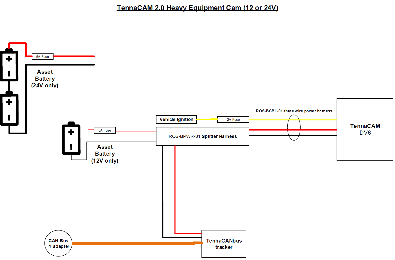
Installation Instructions
Step 1. Link the TennaCANbus tracker to the asset in the Tenna App.
- Go to where the asset is located (so that you can see and touch the vehicle).
Pro Tip! Being in physical proximity to the asset helps ensure that you link the tracker to the intended asset.
- Open the Tenna App on your mobile device and log in.
- In the Tenna App, select the camera icon to open the QR scanner.

- Scan the QR code on the TennaCANbus tracker.

- Follow the prompts along with these installation instructions.
Step 2. Begin installation of the TennaCANbus tracker.
Pro Tip! For best results, park the asset in a location with an unobstructed view of the sky.
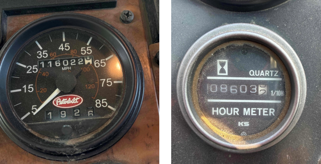
- Input the asset’s hour meter and/or odometer reading.
📸 Capture Hour Meter/Odometer Photo in Tenna App
At this point, you will be required to capture a photo of the asset's current reading on the odometer. This is important for verifying the reading at the time of installation and troubleshooting in the future. Make sure the photo is clear (not blurry) and well-lit.
- Turn off the ignition and remove the key from the ignition switch. Not doing so will result in a failed installation.
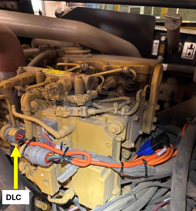
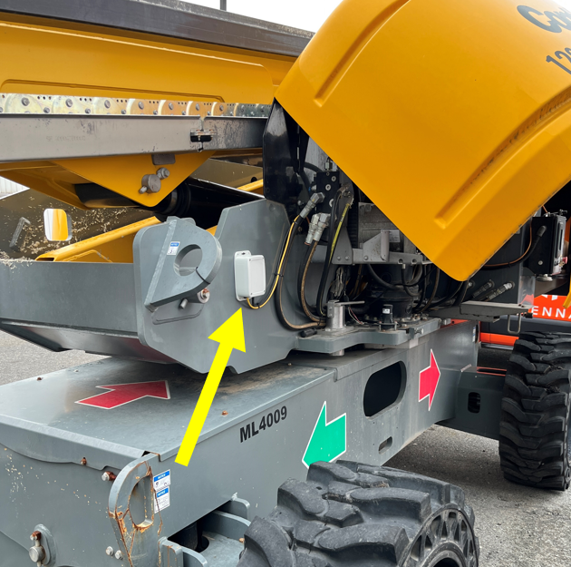
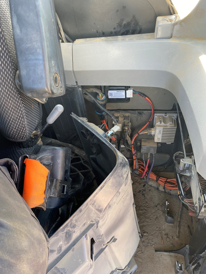
- Locate the machine’s DLC (Data Link Connector).
NOTE: In most machines, the DLC is located in the cab. You may also find the DLC in an outside fuse panel or behind an access door. In the event of more than one DLC, always connect to the Engine DLC.


Important! Some assets may have two DLCs:
- Caterpillar Backhoe
- Leibherr Crane
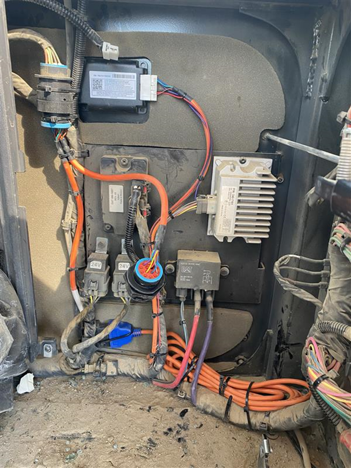
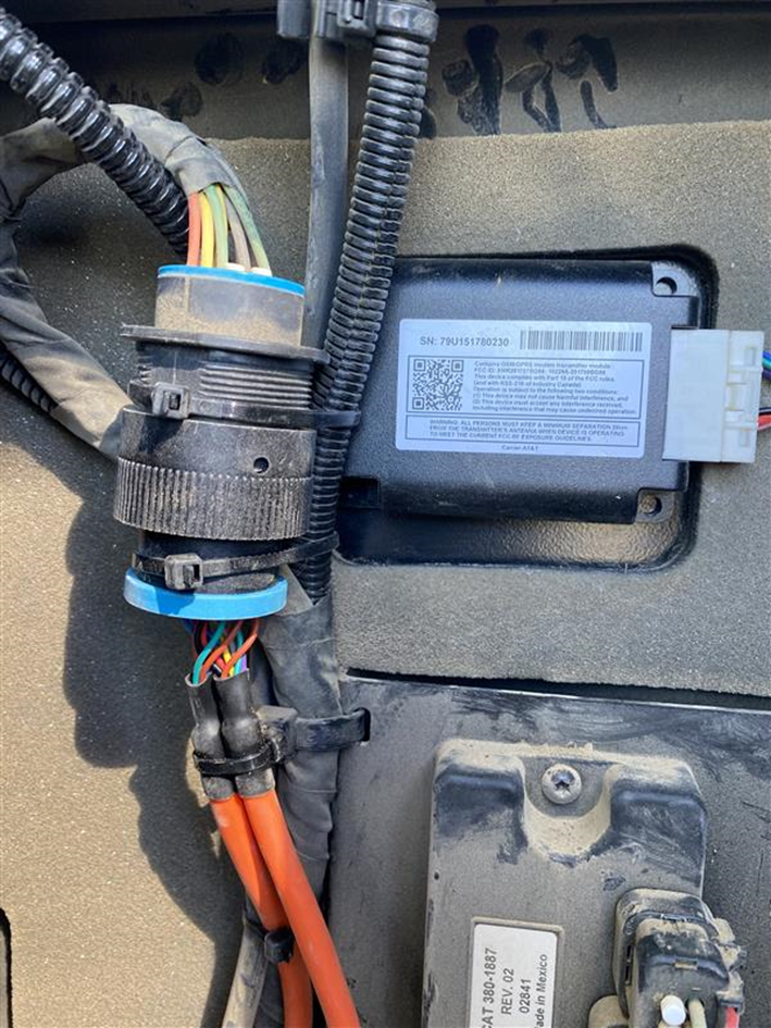
If installing to Caterpillar Backhoe with the DLC mounted/soldered in the PCB board (as pictured below):

DO NOT INSTALL TO THIS DLC. Prior to install, your Tenna Rep will have confirmed the asset's serial number and provided the correct 9-pin or 14-pin Y-adapter that can be connected to a second/different DLC in the machine. Locate the second DLC and complete the installation there.
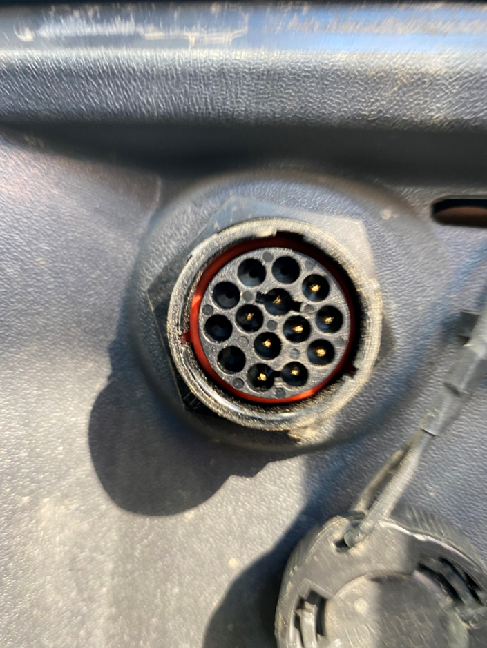
If installing to a Leibherr Crane with a FMS 12-pin DLC (pictured below):

DO NOT INSTALL TO THIS DLC. Prior to install, your Tenna Rep will have confirmed the asset's serial number and provided the correct J1939 Y-adapter that can be connected to a second/different DLC in the machine. Locate the second DLC and complete the installation there.
📸 Capture Photo of the DLC
This is important for troubleshooting in the future.
- Take a close-up photo of the DLC before connecting to show the number of pins.
- Take a photo further back to show where the DLC is on the asset.
- If the DLC is mounted outside of cab, and exceeds the length of the tracker harness (GMS-YZKB-02) needed to easily mount the TennaCANbus tracker in a serviceable location within the cab, then a Tenna StormBox will be necessary. Follow the next steps to install the Tenna StormBox.
Note: If not using the Tenna StormBox, skip to Step 4.
Step 3. Install the Tenna StormBox (optional)
- Identify the location where you will install the Tenna StormBox and note where the bottom of the box will sit.
- Install the included steel plate to the interior of the Tenna StormBox with the provided screws.

- Drill a 1” hole on the bottom, left side of the Tenna StormBox. Then, drill a 1/2” hole on the bottom, right side of the Tenna StormBox.

- Route the white connector of the TennaCANbus harness through the 1” hole. Make a cut in one half of the larger grommet included with the Tenna StormBox. Install the grommet over the orange cable of the harness.

- Install the smaller grommet in the ½” hole. Guide the extra length of power and ground wires into the Tenna StormBox from the bottom (through the smaller grommet).

- Within the Tenna StormBox, connect the power and ground wires to the power and ground cables on the tracker harness using the appropriate length of 14/2-gauge cable and the appropriate heat shrink connectors (making sure all connections will be protected by the Tenna StormBox once these are completed and the Tenna StormBox is closed).
📸 Capture StormBox Photos (if applicable)
This is important for troubleshooting in the future.
- Take a picture of the TennaCANbus inside the Stormbox with cover off and wired
-
Ensure the wiring comes into the Stormbox from the bottom

Step 4. Continue TennaCANbus installation.
Important! Be careful not to bend any pins when you plug the tracker or adapter into their respective sockets. Always mate connectors straight on-axis to prevent mis-mating and pin damage.
- Remove the asset’s OEM DLC and replace it with the provided Tenna Y Adapter (bulkhead end). Secure in place.

- Secure the OEM DLC harness socket to the plug end of the Tenna Y Adapter (non-bulkhead fitting end).

- Connect the TennaCANbus tracker harness’ positive (red) and negative (black) wires directly to the positive (red) and negative (black) wires of an available leg (other than the battery leg) of the Power/Ground splitter harness using the correct size butt connectors.

Important! All ground connections must connect to the supplied power/ground splitter harness and not the chassis ground. If connected anywhere other than the power/ground splitter harness, Parking Mode will not work if the battery disconnect is turned off.
- Route the battery leg of the power/ground splitter harness directly to the battery area using the 14/2-gauge wire at the needed length.

- Connect the black wire of the battery leg of the power/ground splitter harness directly to the battery’s negative post by installing the correct size electrical terminal.
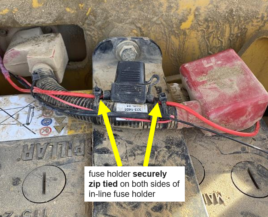
- Then, connect the red wire of the battery leg of the power/ground splitter harness to the battery’s positive post using the supplied in-line fuse holder with a 5-amp fuse and the correct size electrical terminal.

NOTE: GROUND - On 24V equipment there are two 12V batteries. The black (ground) wire of the tracker harness must connect directly to the actual battery ground (0V) post that usually runs to the battery disconnect/chassis ground. Not doing so will cause the camera system to not work correctly.

Important! Do not connect the black wires to a chassis ground or any other ground connection. Doing so will affect the tracker and camera operation if the master battery disconnect is turned off.
NOTE: POWER - On 24V equipment there are two 12V batteries. The red wire must connect directly to the actual battery post that provides 24V and not to the battery that provides 12V at the cross over battery cable post. A multimeter should be used to check both battery positive posts and connect to the battery that reads 24V with the meter’s ground lead connected to the battery ground post that connects to the ground cutoff switch. Not doing so will cause the TennaCANbus and camera system to not work correctly.

- Use cable ties to secure and protect all wires away from moving parts, sharp edges, and heat sources.
📸 Capture a Photos of the Connections to the Battery
This is important for troubleshooting in the future.
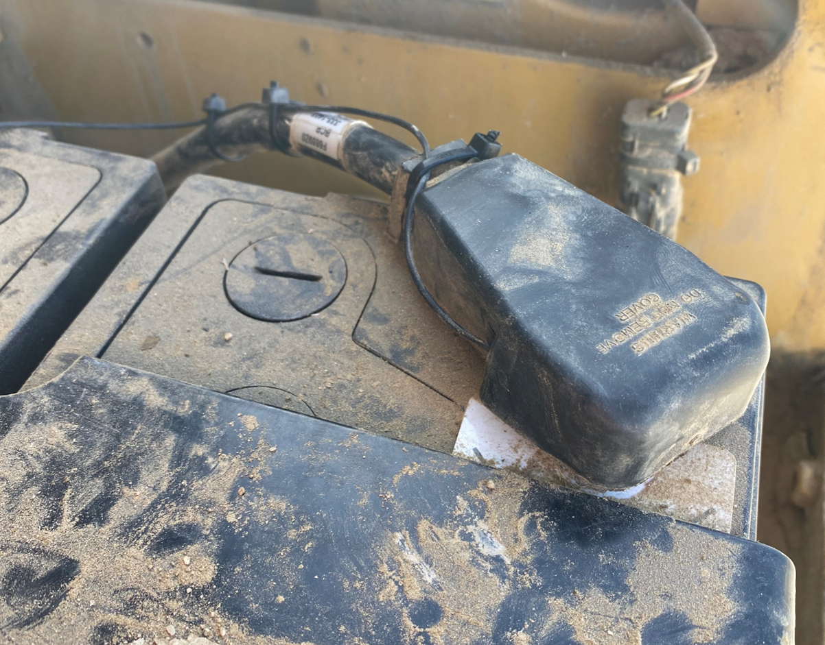
- Take a picture of the power wire connection with fuse holder securely zip tied on both sides of in-line fuse holder and inline fuse mounted as close to positive battery terminal as possible
- Take a picture of the ground wire connection at the battery with zip tie on lead
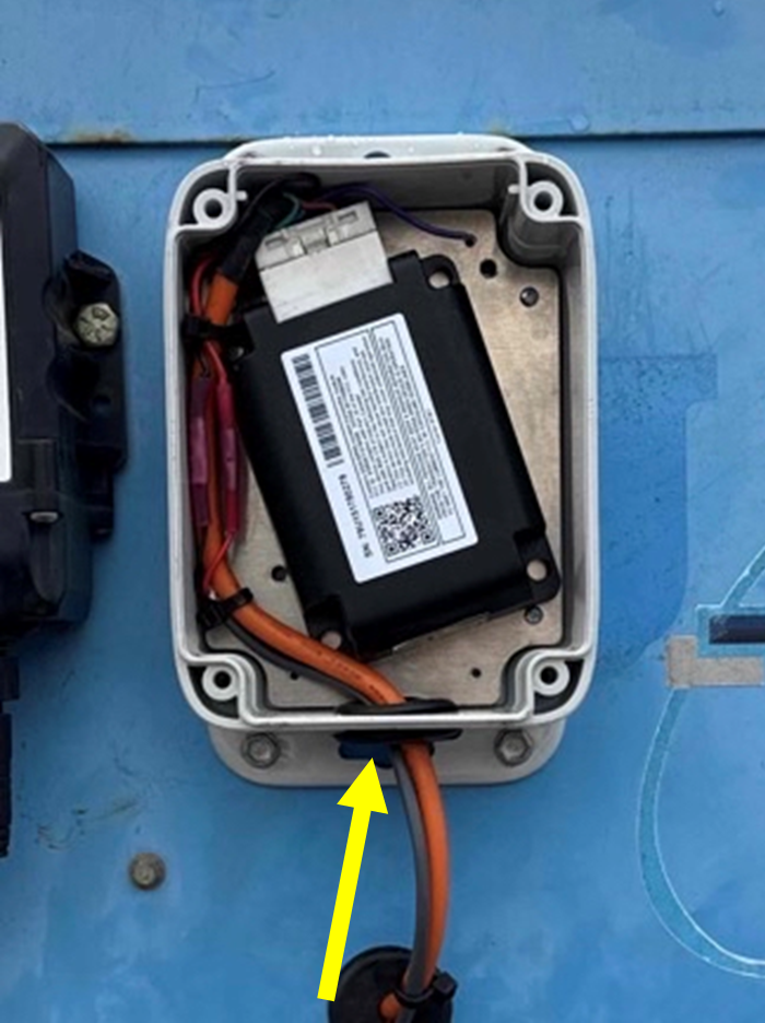
- Plug the adapter’s 16-pin (OBD style) socket into the tracker harness’ blue, 24V OBD plug.

- Carefully plug the harness’ 20 pin (white connector) into the TennaCANbus tracker. Push firmly until locked in place. Do not force the white connector to avoid bending pins or causing damage.
- If using a Tenna StormBox, connect the TennaCANbus tracker to the harness inside the StormBox.

📸 Capture Power Source Photo in Tenna App
At this point, you are required to capture a photo of the Power Source in the Tenna App. This photo is very important for troubleshooting in the future. When taking a photo, remember the following:
- Make sure the photo is clear (not blurry) and well-lit
- Make sure you can see all connections clearly, including fuses (if applicable)
- If multiple photos are supported, upload one close up of the connections and one zoomed out to show where you made the connection.
Step 5. Mount and activate the TennaCANbus tracker.
- Using an acetone based cleaner, remove dirt and debris from the selected mounting location within the cab of the equipment. Make sure that the selected location has a clear view of the sky.
- Remove the protective layer from the VHB tape on the back of the tracker.

- Mount the tracker to the cleaned and dried location. Press the tracker into the mounting location and hold for 30 seconds to set the adhesive bond.

Important! To ensure proper adhesion, only apply VHB tape in temperatures above 50°F and to previously cleaned surfaces. If needed, careful use of a butane torch is recommended to heat sheet metal mounting surfaces in lower temperatures. Exercise caution with open flames to prevent accidents.
If installing using a Tenna StormBox:
- Mount the tracker to the steel plate within the case.
- Screw the Tenna StormBox cover onto the bottom half of the case, making sure that the wires inside of the Tenna StormBox are not pinched.
Important! Do not overtighten the Tenna StormBox screws but make sure that they provide good pressure to the Tenna StormBox cover so it is protected from the elements.

- Mount the Tenna StormBox to the asset using screws or VHB tape.
📸 Capture StormBox Photos (if applicable)
This is important for troubleshooting in the future.
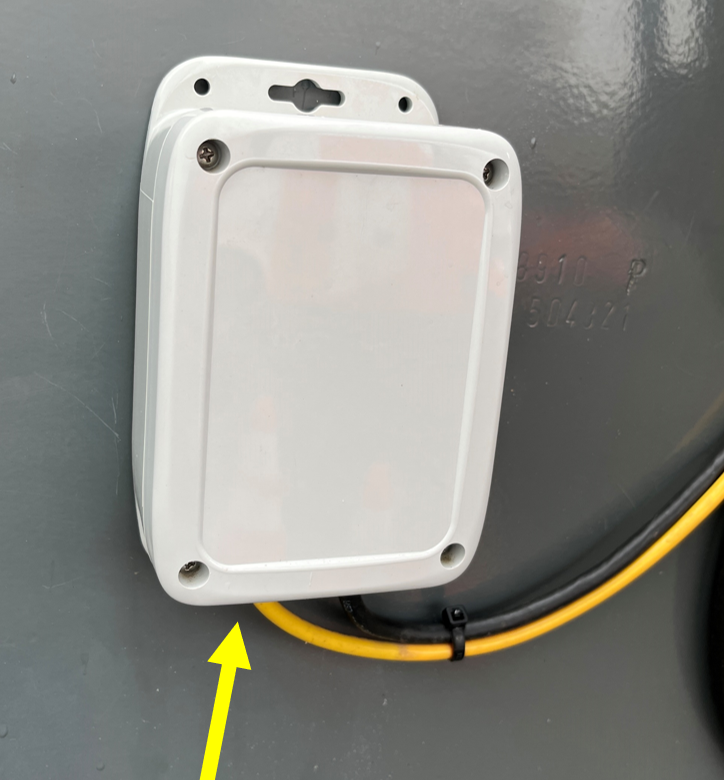
- Take a close up photo of the enclosed StormBox.
- Ensure the wiring comes into the StormBox from the bottom.
- Take a photo further back to show the StormBox mounting location on the asset.
- Use cable ties to secure the adapter or extension cable to a stationary part of the asset so the tracker, harness, and adapter cannot move. Ensure that the cabling cannot flail about in the wind or catch on passing personnel or equipment.
Important! If installing external PTO, view Installation Instructions: External PTO.
📸 Capture Installation Photos
This is important for troubleshooting in the future.
- Take a picture of the general wire routing securely mounted with zip ties
- Take a close-up picture of the mounting location of the tracker before replacing any removed panels
- Take a picture further back so it makes it clear where on the asset tracker is mounted
- Take a picture of the PTO (if applicable)
Step 6. Begin installation of the TennaCAM 2.0 Heavy Equipment camera in the Tenna App.
- Enter the serial number for the asset in the Tenna App.
- Enter or scan the IMEI on the bottom of the camera in the Tenna App.

Step 7. Install the TennaCAM 2.0 Heavy Equipment camera.
- Determine the best location to mount the camera .
Pro Tip! The best place to mount the camera is the top, center of the windshield. Ensure that the camera will always have a clear view of the operator and the outside, clear of wiper blade reach, sunshades, rearview mirrors, or any other obstructions. If the center of the windshield is not available, choose a location on the windshield that meets the previous requirements.

- Thoroughly clean, dry and prime the windshield at the intended installation location with the supplied alcohol pad and 3M primer stick. The primer should be applied to the entire area covered by the camera mounting tape. Let the primer air dry.
Important! If the primer is not used, the camera installation will fail and camera will fall off the windshield.
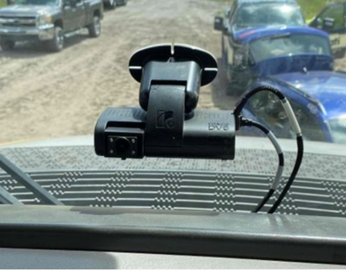
- To apply the camera to the windshield, remove the protective film from the adhesive pad and firmly press and hold the mount to the prepared section of the windshield for at least one minute to set the bond. Make sure the camera is parallel to the ground as seen below:

- Adjust the camera angle. Use the T20 wrench to loosen the center mounting bolt and set the camera so the bottom surface of the camera is parallel with the ground. Tighten the mounting bolt so that the camera does not move.

- Using the supplied T8 wrench, loosen the two screws on the right side of the camera to remove the security panel. The screws are captive to the cover plate so that they do not get lost.

Step 8. Install the camera's 3-wire power cable (ROS-BCBL-01) (DV673).
Important! TennaCAM 2.0 Heavy Equipment needs to be powered directly from the battery so that special features work while the ignition or machine’s battery disconnect is turned off. Not following the installation instructions will have a negative effect on the camera’s features.
- Insert the harness plug into the power port on the right side of the camera. Ensure that the green dot is facing up with the connector key ridges face up.

- Carefully push the connector straight and all the way into the socket to ensure a good connection. Then, route the cable up and out of the cable exit hole cutout in the casing of the camera.
- Re-attach the side cover. Make sure that the power harness strain relief is placed without being pinched. Use a T8 wrench to tighten and secure the side cover . The cable should be snug and secure.

- Connect the red (battery) wire of the DV673 camera harness (ROS-BCBL-01) to the red wire of an available leg of the power/ground splitter harness using the correct size electrical butt connector.

- Connect the black (ground) wire of the DV673 camera harness (ROS-BCBL-01) to the black wire of the same available leg of the Power/Ground splitter harness.

- The remaining legs of the power/ground splitter harness will not be used. Install protective covers and tape up for safety.
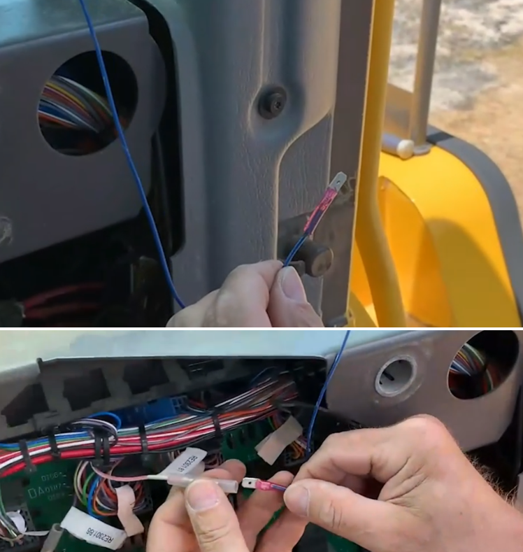
- Connect the DV673 camera harness (ROS-BCBL-01) yellow wire to the machine’s ignition source. Install a 2A fuse to protect the camera ignition circuit.
Important! When using an add a fuse, never use a circuit powering an ECM or Powertrain Controller, or any other circuit that is closely monitored by the asset’s systems for current flow. It is recommended to only use less important, higher current circuits, such a horn or radio, to minimize the chance of the vehicle’s onboard diagnostics generating inappropriate error codes.


📸 Capture Ignition Wiring Photo
At this point, you will be required to capture a photo of the Ignition wire connection with fuse holder/add-a-fuse securely zip tied. This is important for troubleshooting in the future. Make sure the photo is clear (not blurry) and well-lit.
- Take a picture of the camera ignition wire connection with add-a-fuse lead zip tied
- If using an in-line fuse, take a photo of the fuse holder securely zip tied on both sides of the fuse socket
Step 9. Test and verify the TennaCAM 2.0 Heavy Equipment camera.
- Start the asset and let it idle for 5 minutes in an area with good cellular reception and good sky view to permit the GPS system to establish a position lock.

- Let the TennaCANbus tracker and camera power up. The camera’s LED light boot cycle is:
- All 3 LEDs flashing
- Green LED flashing
- Green LED steady
NOTE: If the camera requires a firmware upgrade, you may see two power cycles before the green light stabilizes. The boot cycle will happen up to 3 times. Wait until the green LED is steady for 30 seconds before continuing.
NOTE: All 3 LEDs may remain on during initial installation.
- Wait while the system verifies that the camera has been registered successfully. This may take up to 3 minutes. You will see a “Verification Successful” notice with a green checkmark when ready. If verification is unsuccessful, try again. If verification fails a second time, unplug the camera, reconnect it, and try again.

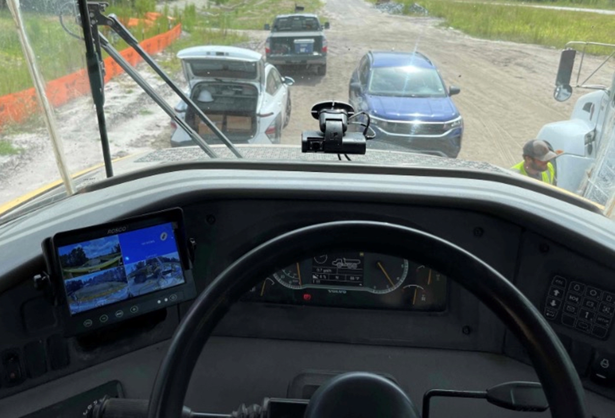
- In the Tenna App, check camera alignment, ensuring that the view is level and not obstructed.
Important! Installers must have the "TennaCAM Reports" and "TennaCAM Videos" permissions enabled in order to see video during this step.
- For Channel 1 (front facing) use the dotted line to ensure the camera is level.
- For Channel 2 (interior facing) adjust the camera so the driver is aligned with the avatar. Then use the T8 wrench to loosen the screws on the bottom and left-side of the camera to adjust the direction of the lenses. Re-tighten.

- Press the driver event button on the dash camera to record a sample video.

- Let the machine run for 15 minutes to verify fuel usage, GPS location, and other cycle data. Park in a spot with good cellular reception and turn the asset off.

📸 Capture Installation Photos in Tenna App
At this point, you are required to capture photos of the installation in the Tenna App. These photos are very important for troubleshooting in the future.
- Take a close up photo of the dash camera installed on the windshield.
- Take a photo further back to show the camera's location on the entire windshield.
Important! Installation photos cannot be changed after the installation process is complete (without restarting the installation process). Ensure all photos are uploaded and correct before completing installation in the Tenna App.
Step 10. Verify the tracker.
- Complete verification steps in Tenna on your desktop computer.
Important! Verification is a critical step in the installation process. Immediately complete verification and follow the steps closely to ensure the camera is working appropriately.
NOTE: If verification is unsuccessful, you will be notified and you may retry. Be sure any error conditions are resolved before trying again; as an example, if no GPS location lock is achieved, (a common issue) make sure the asset is out in the open with good sky view.