TennaCAM 2.0 Fleet Side Cameras Installation
Instructions for installing TennaCAM 2.0 Fleet Side Cameras (#TCM-ABKS-01, #ROS-ARSC-01, #ROS-ALSC-01) to an existing TennaCAM 2.0 Fleet + Fleet Auxiliary Camera system.
Important! Tenna hardware should only be installed by a mechanic who is Tenna Certified for this specific hardware tracker.
Pro Tip! Review our Tracker Installation Best Practices before installing a Tenna tracker.

In this article:
Safety Information
WARNING
- Follow established safety precautions for operating and servicing the equipment on which you are installing this Tenna product.
- Do not mount any devices or run any cabling which may interfere with an asset’s safety guards or shields.
CAUTION
- Re-tighten any screws loosened during installation.
- Replace any safety devices removed during installation.
Important Installation Notes
- TennaCAM 2.0 Fleet Side Cameras may only be installed as accessories to a TennaCAM 2.0 Fleet Auxiliary Camera.
- Complete the TennaCAM 2.0 Fleet Auxiliary Camera installation instructions prior to installing the side cameras.
- Keep asset ignition OFF until instructed otherwise.
Tools and Materials Required
- Drill
- 5/8" drill bit
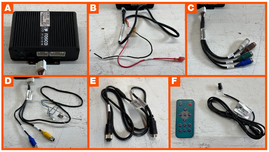
Hardware Included
- TennaCAM 2.0 Side Cameras:
- Left Side Camera (STSC268) (#ROS-ALSC-01)
- Right Side Camera (STSC267) (#ROS-ARSC-01)
- (2) Mounting brackets and self-tapping screws
- Allen screws and Allen tool
- Multiplexer Kit (STSS1200) includes:
- Multiplexer Box (STSS1200MO)
- Power Harness (STSS1200PHAR)
- Video Input Harness (STSS1200VHARA)
- Video Output Harness (STSS1200VHARB)
- Video Magnification Harness (STSH415)
- IR receiver cable (STSA1036) and IR remote (STSA1035) Not required in this installation
- (2) 16.5' Video Cables (STSH345)
Installation Diagram

Installation Instructions
Step 1. Identify an appropriate mounting location for the Multiplexer Box.
Adequate space is needed to mount the Multiplexer Box (STSS1200MO) along with the associated harnesses and video cables in the Multiplexer Kit . Identify an appropriate location under the dashboard that is out of the way of the driver and where it will not be damaged or unplugged.
Step 2. Find a good, clean, solid ground source.
Run and connect the black wire of the Multiplexer Power Harness (STSS1200PHAR) to the identified ground source.
NOTE: The wire marked “ground” on the installed TennaCAM 2.0 (DV6) harness can be used.

Step 3. Locate the previously installed TennaCAM 2.0 Auxiliary Camera Relay Harness (SWI6027) (connected to the DV607 Converter Box.
Connect the red wire (marked “ACC +”) on the Multiplexer Power Harness (STSS1200PHAR) to the green wire (marked “+12 volt Power to STSS1200”) on the TennaCAM 2.0 Relay Harness (SWI6027).

Step 4. Plug the Multiplexer Power Harness (STSS1200PHAR) into the DC Power Input Connector (marked “DC IN”) on the Multiplexer Box.
Make sure the plug is seated and locked securely.

Step 5. Identify appropriate locations on both the left and right sides of the asset to mount each of the side cameras.
Important! Do NOT mount the side cameras to any moving parts, with the exception of doors with limited motion. Do not mount cameras to parts of an asset that rotate, separate from the cab, or otherwise could pull, damage, and unplug the cables.
Step 6. Temporarily mount the cameras with VHB tape.
Pro Tip! We recommend that you temporarily mount the side cameras in the desired location using VHB tape. This will give you the opportunity to verify the live view is optimal before permanently mounting the side cameras to the asset.
Each side camera is designed for use on a specific side of the asset:
- Left Side Camera (STSC268) (#ROS-ALSC-01)
- Right Side Camera (STSC267) (#ROS-ARSC-01)
Each camera is also marked with a red arrow visible inside the ring of IR LEDs that must face upwards for proper camera orientation. See image below showing orientation arrow circled.

Step 7. Connect the side cameras.
Connect the 16’ Video Cables (STSH345) to each of the side cameras.
Run the 16’ Video Cables (STSH345) into the cab through a protected access point (like a grommet) and to the Multiplexer Box.
Important! Avoid any pinch or tug points, or areas that may result in cable damage, stress, or risk of being unplugged. Make sure all cables are secure and away from moving parts.
Step 8. Connect the Multiplexer Box.
Connect the Multiplexer Video Input Harness (STSS1200VHARA) to the port marked "Camera 1-4" on the Multiplexer Box. Push to click to ensure it is secure.

Connect the left side camera, 16’ Video Cable (STSH345 to the connector marked “CAM3” on the Multiplexer Video Input Harness (STSS1200VHARA).

Connect the right side camera, 16’ Video Cable (STSH345) to the connector marked “CAM4” on the Multiplexer Video Input Harness (STSS1200VHARA).

Important! Each side camera must be connected to the correct multiplexer port (Left to CAM3, Right to CAM4). If not, cameras will be reversed when viewing footage online or on the optional Auxiliary Monitor.
Unplug the TennaCAM 2.0 Auxiliary Camera Video Cable from the port marked “Video In” on the DV607 Converter Box and instead plug it into the connector marked “CAM1” on the Multiplexer Video Input Harness (STSS1200VHARA).

NOTE: TennaCAM 2.0 Auxiliary Camera MUST connect to the “CAM1” connector to be able to hear the Auxiliary Camera audio on the monitor’s speaker.
Connector “CAM2” is not used in this system.
Connect the Video Output Harness (STSS1200VHARB) into the connector marked “PERIPHERAL” on the Multiplexer Box.

Note: The following are not used in this install and should be tied back safely:
- Wires marked “TRIGGER" and "CVBS”
- Harness marked “STSA1036”
- The supplied remote “STSA1035” is not used in this installation and should be stored away.
Connect the Video Magnification Harness (STSH415) to the connector marked “AHD” on the Multiplexer Video Output Harness (STSS1200VHARB).
Connect the other end of the Video Magnification Harness (STSH415) into the DV607 Converter Box “Video In” port.
Step 9. Check camera alignment and view.
Turn the asset’s ignition on and open the live stream in Tenna.
DV607 LED Light Behavior
Both LED lights (blue and green) on the DV607 should illuminate when the asset's ignition is on. It may take a few moments for the dash camera and DV607 to finish start up. Once the dash camera's LED lights show solid green, both lights on the DV607 should be illuminated.

- Troubleshooting:
- If the green light does not illuminate, troubleshoot for an issue with the power or ground sources.
- If the blue light does not illuminate, ensure the video extension cable (STSH345) is connected improperly.
Multiplexer LED Light Behavior
The red Power light and 3 green Channel lights (CH1, CH3, and CH4) should illuminate on the Multiplexer when the asset's ignition is ON.

- Troubleshooting:
- If the red Power light blinks and then turns off, the Multiplexer might be faulty. Contact Tenna Support.
- If the green CH 2 light is illuminated (and one of the other channels is not illuminated), the Multiplexer Video Input Harness (STSS1200VHARA) has been connected improperly.
The Auxiliary and Side Cameras will show in Source 3. This may take a minute after the ignition has been turned on and the green LED on DV6 has stopped flashing.
NOTE: Side Cameras do not require separate verification. All additional cameras (Auxiliary and Side Cameras) should show a live stream on a single channel, Source 3, as seen on Tenna Online once correctly connected and the asset’s ignition is on.

Adjust the camera(s) as needed to optimize the view.
Step 10. Permanently mount the side cameras.
Mark the desired mounting locations using the mounting bracket and tracing the outline for the video cable access holes to be drilled.

Drill 5/8” holes in marked location.

Use the provided self-tapping screws and gaskets to install the mounting brackets on each side of the asset.

Guide camera’s cable through the bracket holes. Secure the cameras to the mounting brackets with the Allen head screws and tool provided.

NOTE: If the side cameras are temporarily mounted, you will need to unplug each side camera from the extension cable (STSH345). Guide each cable through the drilled hole and reconnect to each side camera.
Step 11. Ensure that all connections are tight and secure.
Route and tie up any loose wires, keeping them out of the driver’s way or moving parts, and preventing any pinch or tug points.

Step 12. Finalize verification and installation.
- Confirm the installation process steps by clicking the verification check box.
- Verify the tracker on Tenna Online.
TennaCAM 2.0 Side Cameras are successfully installed.
If you are installing an Auxiliary Monitor, view TennaCAM 2.0 Auxiliary Monitor Installation.