TennaMINI 2.0 Plug-In Solar Tracker Installation
The below are installation instructions for installing the TennaMINI 2.0 Plug-In Solar (#BEW-PLMT-PA) tracker.
Important! We strongly recommend that Tenna hardware only be installed by a Tenna Certified mechanic. Contact your Tenna Rep to learn more about our Mechanic Certification program.
Pro Tip! Review our Tracker Installation Best Practices before installing a Tenna tracker.
In this article:
Safety Information
WARNING:
- Follow established safety precautions for operating and servicing the equipment on which you are installing this Tenna product.
- Do not mount any devices or run any cabling which may interfere with an asset’s safety guards or shields.
- If splicing into the asset’s existing onboard wiring is the only option, do not wire into any safety devices or sensors (for example, a tilt sensor on a crane or man lift).
CAUTION:
- Retighten any screws loosened during work.
- Replace any safety devices removed during work
Installation Notes
- For best results, mount the tracker in an unenclosed location so that its top surface has an unobstructed view of the sky.
- To ensure proper adhesion, only apply VHB tape in temperatures above 50°F. Butane torch recommended for lower temperatures to heat mounting surface.
- If screws are used to mount this Tenna product to the asset, ensure that the back side of the mounting location provides adequate clearance. Be careful not to drive screws into coolant lines, radiators, electrical wiring, fluid tanks, or moving components.
- In the case of a battery connection which is in series, the power supply for the tracker should be drawn across the full stack rather than just one battery.

Tools and Materials Required
- Mobile device with Tenna App installed
- Impact Driver with 5/16” bit
- 1-inch diameter step drill bit
- Digital multimeter
- Crimpers, strippers, and cutters
- Heat gun for shrinking heat-shrinkable splices and terminals to protect against weather
- Ring terminals for 18-gauge wire (crimp-on; heat-shrinkable to protect against weather)
- Butt-joint splices for 18-gauge wire (heat-shrinkable)
- Cable ties and automotive wire harness tape
- Acetone-based cleaner
- Clean, absorbent rags or towels
- Misc. heat shrink wire terminals
- add-a-fuse holder and correct size fuse
- TennaTEST (optional)
- Materials for your chosen mounting method (screw, magnet, or tape) as listed below
- For screw mounting:
- Stainless steel self-tapping screws (included)
- Impact Driver with 5/16” bit
- For magnet mounting:
- Mounting kit (includes 4 magnets) (#CAT-MKIT-4M) *Must purchase in advance from Tenna
- Phillips screwdriver
- 8-mm wrench or socket
- For tape mounting:
- Cutting tool (scissors, side cutters, or knife)
- 3M VHB Tape 4932 (or equivalent)
- Butane torch to heat surface (if installing in temperatures below 50°F)
- 3m primer pen
- For screw mounting:
Hardware Included
- TennaMINI 2.0 Plug-In Solar
- #10 x 1” 304 stainless self-tapping screws (4) with nylon washers
- TennaMINI Installation Cable Kit (CAT-PLGI-CK):
- (A) Tracker power cable (red and black leads)
- (A1) 3-amp fast-blow ATC blade-type Fuse
- (A2) Fuse housing
- (A3) Connector to breakout cable
- (B) Ignition cable (white)
- (B1) 3-amp fast-blow ATC blade-type Fuse
- (B2) Fuse housing
- (B3) Connector to breakout cable
- (C) Breakout cable
- (C1) Connector to tracker
- (C2) Connector to ignition cable
- (C3) Connector to tracker power cable
- (D) M8 Cable
- (A) Tracker power cable (red and black leads)

Installation Steps
Step 1: Link the Tracker to the asset in the Tenna App
- Go to where the asset is located (so that you can see and touch the asset).
Note: Being in physical proximity to the asset helps ensure that you link the tracker to the intended asset.
2. Open the Tenna App on your mobile device and log in.
3. Using the Search function, find and select the asset that you want to track with this tracker.
4. From the Asset page, tap Add Tracker.
5. Follow the prompts along with these installation instructions.
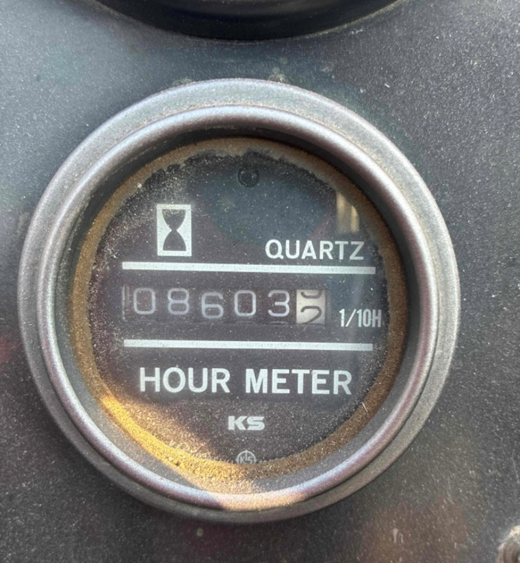
6. Add Hours: Observe your machine’s hours and input the hours when prompted.
📸 Capture Hour Meter Photo in Tenna App
At this point, you will be required to capture a photo of the asset's current reading on the hour meter. This is important for verifying the reading at the time of installation and troubleshooting in the future. When taking a photo, remember the following:
- Make sure the photo is clear (not blurry) and well-lit
- Make sure you can read the numbers in the photo
Step 2: Determine the location on the asset to install the tracker
Note: For best results, mount the tracker in an unenclosed location so that its top surface has an unobstructed view of the sky.
- Select the best location for the tracker:
- Horizontal mounting is ideal (for example, on the roof of the equipment cab).
- Vertical mounting is acceptable provided that the top of the tracker has a clear view of the sky.
- Choose a location where the tracker is unlikely to be damaged or knocked off during normal operation of the asset.
- You can place the tracker inside the operator cab of the equipment, but do not install it under the dash or in any place where there is poor sky visibility.
- If you must enclose the tracker, use nonmetallic housing and ensure that the tracker has good RF signal sky visibility through the enclosure. The tracker will not function well when placed inside a metal cabinet or case, or on the underside of the equipment.
Important! If enclosed or mounted under the equipment, the tracker will not charge from the sun.
- If you use screws to mount the tracker, choose a location that is not backed by any component that the screws could damage, such as coolant lines, radiators, electrical wiring, fluid tanks, or moving components.
- You must be able to route the cables from the tracker to the battery and ignition contact safely. Ensure there is:
- No possibility of wire pinching
- No interference with moving parts
- No unsecured cable run
- No swinging or dangling cable
Step 3: Clean the selected location
- Scrape any loose debris from the surface.
- Use the acetone-based cleaner to remove grease, oil, and dirt from the mounting location.
- Wipe the area dry with a clean, absorbent rag or towel.
Step 4: Activate the tracker
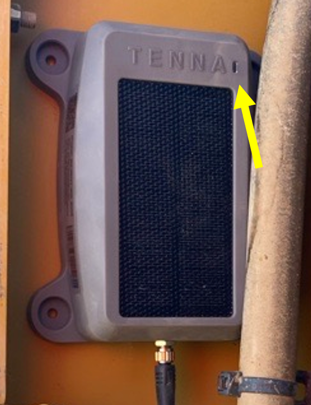
Important! The TennaMINI 2.0 Plug-In Solar trackers ship with a light blocking sticker secured to the top of the tracker. This sticker must be removed from the tracker to activate it.
- Remove the sticker located at the top of the device covering the light sensor.

- Hold the device’s light sensor up to direct sunlight for three seconds before mounting.

Step 5: Find sources for ground, ignition, and continuous power.
NOTE: This tracker can accept mixed voltage inputs between 12 volts and 24 volts.
- Ensure that the equipment’s ignition is in the off position.
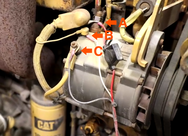
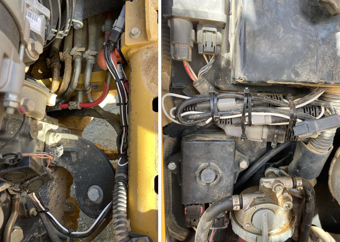
- Using the multimeter, identify an optimal source for ground, ignition and continuous power: the alternator or a fuse point.
Important! The alternator is the suggested and best source for continuous power, ground and ignition. Measure voltage at the alternator first.
- Touch the negative probe of the multimeter to a good, clean, shiny metal ground connection.

- Touch the positive probe of the multimeter to an alternator terminal or fuse point.
- A continuous power source will read voltage when the asset’s ignition is in the on or off position.
- An ignition source will read voltage only when the ignition is turned on and will read 0 when the ignition is turned off.
Step 6: Connect the tracker power cable to power and ground.
Strip and tightly twist the loose ends of the red and black wires on the tracker’s power cable.
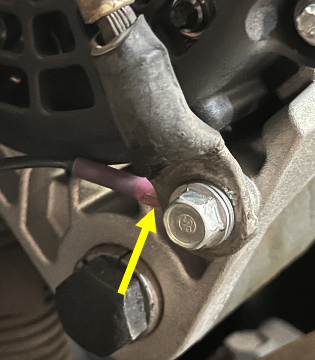
- If connecting to the alternator, crimp ring terminals onto the stripped wire ends.
Note: Use a size that matches the size of the screws or studs to which you are connecting. The terminals must be compatible with 18 AWG wire.

- Heat-shrink the insulation on the ring terminals until watertight.

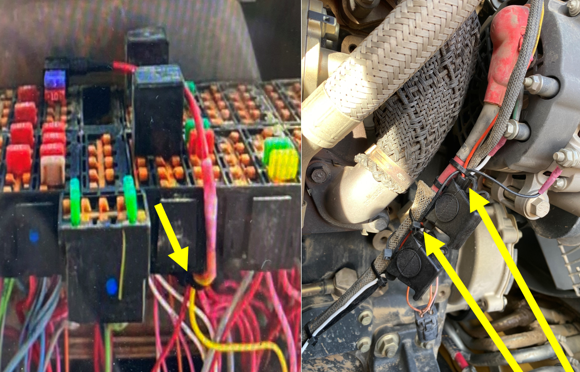
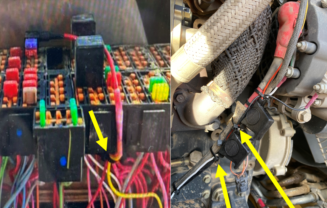
- If connecting to the fuse panel, install an Add-a-Fuse to the red wire on the tracker’s power cable.

- Connect the black wire of the tracker’s power cable to the asset’s ground connection (C).
Important! If your asset has a battery disconnect switch, do NOT wire the ground wire directly to the battery. The ground wire must be connected to a chassis ground.
- Connect the red wire of the tracker’s power cable to asset’s continuous power source (A).
📸 Capture Photo of the Ground Wire Connection in Tenna App
At this point, you are required to capture a photo of the ground source in the Tenna App. This photo is very important for troubleshooting in the future.
📸 Capture Power Source Photo in Tenna App
At this point, you are required to capture a photo of the Power Source in the Tenna App. This photo is very important for troubleshooting in the future.
- Take a picture of the power wire connection with add-a-fuse lead zip tied
- If using an in-line fuse, picture of fuse holder securely zip tied on both sides of the fuse socket
Step 7: Connect the ignition cable to the ignition source.
- Get the ignition (white) cable from the TennaMINI Installation Cable Kit.
- Open the inline fuse housing and confirm that it is empty.
Important! The TennaMINI power and ignition cables each include a weather-protected, inline fuse housing. Make sure that fuses are not installed in the fuse housings prior to connecting the cables to power and ignition sources. Fuses will be installed later in the process.

- Strip and tightly twist the loose end of the ignition cable (white wire).

- If connecting to the alternator, crimp a ring terminal onto the stripped wire end.
Note: Use a size that matches the size of the screws or studs to which you are connecting. The terminals must be compatible with 18 AWG wire.

- If connecting to the fuse panel, install an Add-a-Fuse to the stripped wire end of the white ignition cable.
- Heat-shrink the insulation to provide protection against weather.
- Connect the white wire to the ignition source (B) you identified.
📸 Capture Ignition Wiring Photo in Tenna App
At this point, you are required to capture a photo of the ignition wiring in the Tenna App. This photo is very important for troubleshooting in the future.
- Take a picture of the ignition wire connection with add-a-fuse lead zip tied
- If using an in-line fuse, picture of fuse holder securely zip tied on both sides of the fuse socket
Step 8: Connect the breakout cable.
- Connect the connector on the end of the tracker’s power cable (A3) to the corresponding connector on the breakout cable (C3).
- Connect the connector on the end of the tracker’s ignition cable (B3) to the corresponding connector on the breakout cable (C2).
- Route the remaining end of the breakout cable (C1) toward the tracker’s intended location.
- Connect the end of the M8 cable (D) to the corresponding connector on the breakout cable (C1).
- Screw the other (male) end of the M8 cable (D) to the threaded connection on the side of the TennaMINI 2.0 Plug-In Solar tracker.
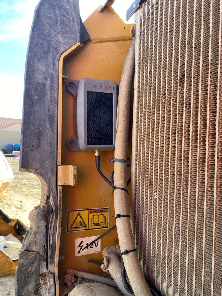
Step 9: Mount the tracker on the asset
Follow the instructions below for screws, magnets, or VHB tape, depending on your preferred mounting method.
IMPORTANT: Do not drive screws into coolant lines, radiators, electrical wiring, fluid tanks, or moving components.
Option 1. Using self-tapping screws
Note: Use the provided self-tapping screws to mount the tracker on steel that is up to 1/8-inch thick. For thicker steel, use machine screws, magnets, or VHB tape.
- Place the tracker in the desired location on the asset.
- Using an impact driver with a 5/16-inch bit, drive the provided stainless steel self-tapping screws through the mounting holes of the tracker into the asset.
- Ensure that each screw is seated securely.
Option 2. Using magnets
Note: Magnet kits must be purchased in advance from Tenna.
Industrial strength magnets are a useful mounting option if the equipment is a rental, if it might be sold, or if you might want to re-purpose the tracker in the future.
- Get magnet kit (CAT-MKIT-4M) and remove the parts from the bag.
- Attach a magnet to the tracker:
- Insert a provided screw into the magnet from the underside (so that the blunt tip of the screw protrudes from the top side of the magnet).
- Insert the screw/magnet combination up through one of the mounting holes of the TennaMINI 2.0 Plug-In Solar (from the bottom of the tracker toward the top).
- Place one of the provided self-locking nuts onto the machine screw where it protrudes on the top side of the tracker; then tighten the nut securely.
- Repeat step 2 to attach each remaining magnet to a mounting hole.
- After you have attached all magnets to the tracker, place the tracker onto the asset at the desired location.

Option 3. Using VHB tape
IMPORTANT: The ambient temperature must be above 50°F to ensure proper adhesion. Butane torch recommended for lower temperatures to heat mounting surface.
- Turn the tracker upside down to expose the underside.
- Measure the VHB mounting tape to cover the entire bottom of the mounting surface. Cut the tape to fit so that it does not extend beyond the ends of the tracker.
- Remove the backing from the VHB tape.
- Following the tape manufacturer’s recommendations, adhere the tracker to the clean, dry surface of the asset.
Step 10: Secure the cables.
- Inspect the wire connections to ensure safe conditions:
- All wires are connected correctly.
- All connections are watertight.
- Inspect the routing for the tracker’s power, ignition, breakout, and tracker cables to ensure safe conditions:
- Cables are not pinched.
- Cables are not exposed to sharp edges.
- Cables are not near a heat source.
- Cables are not near moving parts.
- Cables are not swinging or dangling.
- There are no long, unsecured runs.
Step 11: Install the fuses.
The tracker uses two 3-amp (purple) fast-blow automotive ATC blade-type fuses (provided).

- Locate the fuses provided in the TennaMINI Installation Cable Kit.
- Insert one fuse into the fuse housing on the tracker’s ignition cable; then close the fuse housing.
- Insert one fuse into the fuse housing on the tracker’s power cable; then close the fuse housing.
NOTE: If a fuse blows upon insertion, re-check your work carefully to locate the short circuit. A DMM with resistance measurement function will help locate short circuits.
📸 Capture Installation Photos in Tenna App
At this point, you are required to capture photos of the installation in the Tenna App. These photos are very important for troubleshooting in the future.
- Take a picture of the general wire routing securely mounted with zip ties
- Take a close-up picture showing that the "Peel Here" decal is removed
- Take a set back picture so it makes it clear where on the asset the tracker is mounted
Step 12: Verify the tracker
- Start the asset and run for at least 15 minutes as a test cycle.
- Complete the remaining steps presented in the Tenna App to finalize and verify the installation.
- Open Tenna on your desktop or laptop computer to complete verification. Do so immediately (before running another cycle) to ensure accurate data for your asset.