TennaCAM 2.0 Heavy Equipment Auxiliary Cameras (Rear, Left, Right) Installation
Below are instructions for installing rear and side auxiliary cameras (TCM-ABKS-02) to an existing TennaCAM 2.0 Heavy Equipment system (TCM-ROGM-05, TCM-ROGM-07).
Important! We strongly recommend that Tenna hardware only be installed by a Tenna Certified mechanic. Contact your Tenna Rep to learn more about our Mechanic Certification program.
Pro Tip! Review our Tracker Installation Best Practices before installing a Tenna tracker.
Note: TennaCAM 2.0 Heavy Equipment Auxiliary Cameras are optional accessories to the TennaCAM 2.0 Heavy Equipment. Review installation instructions for TennaCAM 2.0 Heavy Equipment prior to installing auxiliary cameras.
In this article:
Safety Notices
Warning!
- TennaCAM 2.0 Heavy Equipment Auxiliary Camera is only 12-volt compatible. Connecting to a 24-volt source requires the included 24V/12V DC-to-DC converter for operation.
- Follow established safety precautions for operating and servicing the equipment on which you are installing this Tenna product.
- Do not mount any devices or run any cabling which may interfere with an asset’s safety guards or shields. When running video cables from the exterior of the vehicle to the interior take notice of any door hinges, pinch points, or rough edges and move and protect the cables as needed. Cut/pinched cables can result in no video feed. Ensure that all cables/wires are secured away from moving parts, to prevent damage or disconnection. Cables must not dangle in open space or be subject to tangling or catching on tools, equipment, etc.
- Replace any safety devices removed during installation.
Important Installation Notices
- Use heat shrink tubing to protect any unused wire uninsulated ends.
- Only tighten video cable connections by hand. Using pliers and over tightening could cause damage to connectors.
- Always slide weatherproof boots that are provided on the video cable over the connections for added weather protection.
- Request permission from management prior to drilling into the asset. VHB tape is recommended for mounting to the top of asset cabs.
- Temporarily mount auxiliary cameras with VHB tape (to make sure the camera is pointed in the right direction to preview your video feed) before drilling any holes.
Tools and Materials Required
- 5/8” drill bit
- 5-amp add-a-fuse or inline fuse holder
- Purple Thread Locker 222
- Drill
- Phillips screwdriver
For screw mounting:
- Sheet metal self-tapping screws
- Impact driver and correctly sized driver bit for self-tapping screws
For tape mounting:
- 3m primer pen 94 adhesion promoter
- Permatex 29208 The Right Stuff 1 Minute Black Gasket Maker
- 3M 4950/WI15 Scotch 4950 VHB Tape
- Alcohol wipes
- Cutting tool
- Butane torch (if installing in temperatures below 50°F.)
Hardware Included
A. (3) TennaCAM 2.0 Auxiliary Camera (STSC201) (ROS-ABAK-01)
B. (3) Mounting Brackets (STSC101MT )
C. Screws

DV609 Kit (ROS-VADC-01) includes:
D. DV607 Converter Box
E. DV676 Harness
F. DV607PHAR Power Harness
G. SWI6027 Relay Kit

H. (1) 33' Extension Video Cable (STSH343)
(2) 16.5’ Extension Video Cables (STSH345)

I. 24V/12V Voltage Converter (ROS-COVR-01)

J. DV608 Security Cover + Screws (ROS-HTCH-01)

K. Grommet(s)
Multiplexer Kit (STSS1200) (ROS-AMUX-01) includes:
L. Multiplexer Box (STSS1200MO)
M. Power Harness (STSS1200PHAR)
N. Video Input Harness (STSS1200VHARA)
O. Video Output Harness (STSS1200VHARB)
P. Video Magnification Harness (STSH415)
Q. IR receiver cable (STSA1036) and IR remote (STSA1035) Not required in this installation

Installation Diagrams
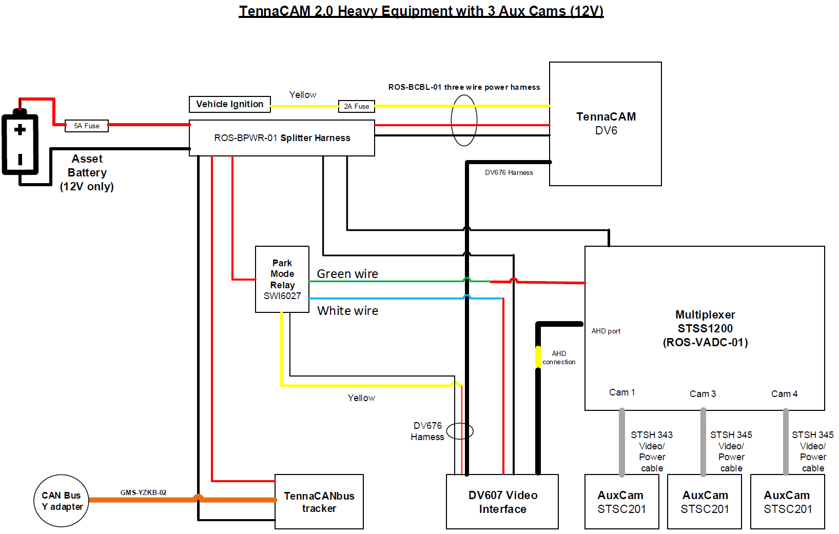
TennaCAM 2.0 Heavy Equipment Auxiliary Cameras (3) for 12V System
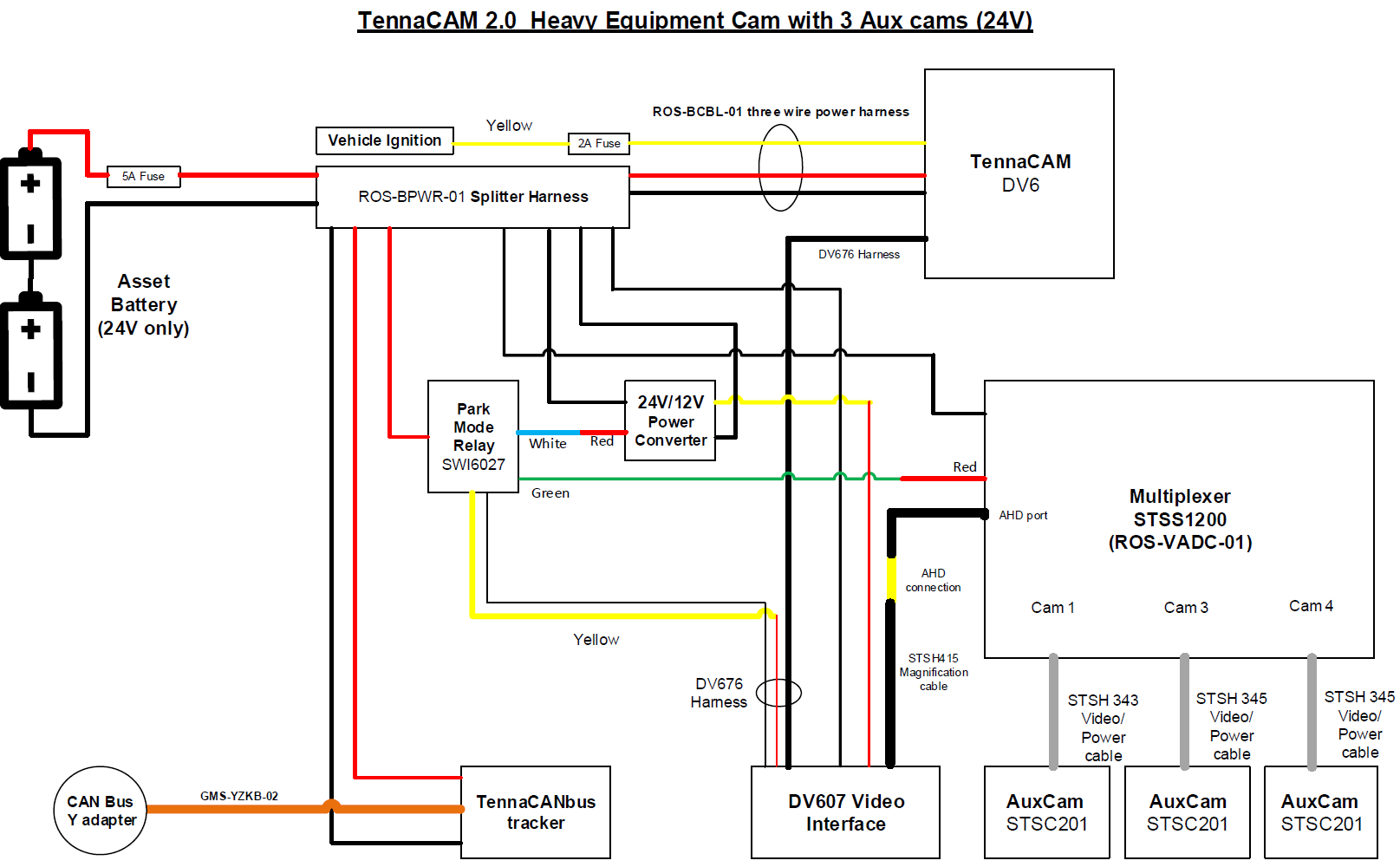
TennaCAM 2.0 Heavy Equipment Auxiliary Cameras (3) for 24V System
Installation Instructions
Step 1. Determine good locations to install the auxiliary cameras.
The best locations should:
- Be on the left, right, and rear of the asset.
- Not be on moving parts of the asset.
- Not obstruct the view of the operator or impede the use of the asset.
- Not cause the view of the camera to be obstructed during use of the asset.
Important! Ensure you have enough extension cable to reach the desired installation locations.
Temporarily mount the cameras in the chosen locations using VHB tape (if mounting on fiberglass/plastic) or with a magnet (if mounting on metal).

Step 2. Identify an interior (or otherwise weatherproof area) to mount the DV607 Converter Box, Multiplexer Box (STSS1200MO), and 24V/12V Voltage Converter (ROS-COVR-01) (if needed).

- Ensure that the chosen location is weatherproof and has enough room to mount the equipment and safely stow cables.
- Ensure the area has access points for wires to reach the asset’s cab and TennaCAM 2.0 Heavy Equipment dash camera, as well as the exterior of the asset to reach the auxiliary camera installation locations. Ensure that the cables can be safely stowed and secured out of the way of personnel, tools and equipment.
- If no access point is found, drill a 5/8” hole and use the provided rubber grommet to make the hole watertight. Do not run the cables through the hole yet.
Important! Ensure you will not drill through important asset lines, like air conditioning, electrical components, cabling, etc.

- Mount the DV607 Converter Box, Multiplexer Box, and 24V/12V Voltage Converter (if necessary). There are two suggested mounting methods:
- VHB Tape: If the surface allows, use VHB tape to mount each box after thoroughly cleaning the surface. Press firmly and hold 30 seconds to ensure proper adhesion.
Note: VHB tape should only be installed on surfaces with a temperature of at least 50°F.
- Screw Mount: Utilize the screw mounting extensions on each box to mount using two sheet metal screws or machine metal screws with nuts (not provided).

📸 Capture Installation Photos
The following photos should be taken for verification and troubleshooting purposes.
- Take a close up photo of the mounted Multiplexer
- Take a close up photo of the mounted DV607
- Take a close up photo of the mounted Voltage Converter


Step 3. Connect the auxiliary camera DV676 Harness to the TennaCAM 2.0 Heavy Equipment dash camera.
- Remove the security panel on the right side of the TennaCAM 2.0 Heavy Equipment using the provided T8 wrench.

- Insert the end of the DV676 Harness into the clip of the security cover (DV608).
Note: All TennaCAM 2.0 Auxiliary Cameras come with a DV608 security cover. If you have an older TennaCAM 2.0 dash camera (DV6), then you should discard the original security cover you removed and replace with the provided DV608 security cover.

- Attach the security cover (DV608) to the side of the TennaCAM 2.0 Heavy Equipment, carefully plugging in the DV676 Harness into the Auxiliary Camera port and routing the power cable through the space on the security cover.
Important! Make sure to observe proper connector orientation and do not force the connector into the socket.
- Secure the security cover (DV608) using the provided T8 screws.
Important! Loosely secured security covers may result in connectivity and video quality issues.
Step 4. Connect the DV607 Converter Box, Multiplexer, and Voltage Converter (if needed).
- Run the DV676 Harness under the asset’s headliner/molding to the DV607 Converter Box and plug it in.

- Plug the Multiplexer Power Harness (STSS1200PHAR) into the DC Power Input Connector (marked “DC IN”) on the Multiplexer Box.

- Connect the power and ground of the DV607PHAR Power Harness to the center port of the DV607 Converter Box.
- Ensure that there is a 5-amp fuse installed in the provided inline fuse holder of the red wire on the DV607PHAR Power Harness. If one is not provided, install a 5-amp fuse.
- Connect the black (ground) wire of the DV607PHAR Power Harness to the black wire of an available leg on the power/ground splitter harness by installing the correct size electrical butt connector.
Important! All ground connections must connect to the supplied power/ground splitter harness and not the chassis ground. If connected anywhere other than the power/ground splitter harness, Parking Mode will not work if the battery disconnect is turned off.
- Connect the yellow and black wires (marked “+5V Trigger In”) on the SWI6027 Relay Kit to the two breakout wires (red and black) of the DV676 Harness.
- Connect the red wire (marked “12V VEH BATT”) of the SWI6027 Relay Kit to a red wire of the on the power/ground splitter harness by installing the correct size electrical butt connector.
- Connect the green wire (marked “+12 volt Power to STSS1200”) on the SWI6027 Relay Kit to the red wire (marked “ACC +”) on the Multiplexer Power Harness (STSS1200PHAR).
- Run and connect the black wire of the Multiplexer Power Harness (STSS1200PHAR) to the black wire of an available leg of the power/ground splitter harness.
Follow the next steps based on if you are installing to a 12V or 24V asset:
For 12V Equipment (no voltage converter required):
- Connect the red wire (marked “BATTERY”) of the DV607PHAR Power Harness to the white wire (marked “+5V PWR toDV607) on the SWI6027 Relay Kit.
- Skip to Step 5: Connect Auxiliary Cameras.
For 24V Equipment:
Warning! TennaCAM 2.0 Auxiliary Camera is only 12V capable. Do not connect to a 24V power source without installing the supplied 24V/12V voltage converter .
- Cut off the red spade terminal end on the white wire (marked “+12V PWR to DV607”) on the SWI6027 Relay Kit and connect to the red 24V wire of the 24V/12V voltage converter (ROS-HTCH-01) using the proper size butt connector.
- Cut off the red spade terminal end on the red wire (marked “BATTERY”) of the DV607PHAR Power Harness and connect to the yellow wire of the 24V/12V voltage converter using the proper size butt connector.
- Connect both black ground wires of the 24V/12V voltage converter to black ground wires on available legs of the power/ground splitter harness.
Step 5. Connect the TennaCAM 2.0 Auxiliary Cameras.
- Connect the 33’ extension cable (STSH343) to the rear-facing auxiliary camera’s harness (attached to the back of the Auxiliary Camera).
- Connect the (2) 16.5’ extension cables (STSH345) to the back of each side-facing auxiliary camera.

- Run all 3 extension cables, through the previously identified access point or drilled hole, to the mounted Multiplexer Box.
Important! Avoid any pinch or tug points or areas that may result in cable damage, stress, or risk of being unplugged. Make sure all cables are secure, neatly dressed and away from moving parts.
Step 6. Connect the Multiplexer Video Input Harness (STSS1200VHARA) to the port marked “CAMERA 1-4” on the Multiplexer Box.
- Push to a click to ensure it is secure. Tug lightly to ensure it does not come out easily.

Step 7. Connect the auxiliary camera on the left side’s extension cable (STSH345) to the connector marked “CAM3” on the Multiplexer Video Input Harness (STSS1200VHARA).
- Hand Tighten the nut to secure the cable lock.

Step 8. Connect the auxiliary camera on the right side’s extension cable to the connector marked “CAM4” on the Multiplexer Video Input Harness (STSS1200VHARA).
- Hand Tighten the nut to secure the cable lock.
Important! Each side camera must be connected to the correct multiplexer port (Left to CAM3, Right to CAM4). If not, cameras will be reversed when viewing footage online or on the optional Auxiliary Monitor.

Step 9. Connect the rear-facing auxiliary camera’s extension cable (STSH343) into the connector marked “CAM1” on the Multiplexer Video Input Harness (STSS1200VHARA).
- Ensure the connection is secure and seated correctly. Hand Tighten the nut to secure the cable lock.
Note: Connector “CAM2” is not used in this system.
Step 10. Connect the Video Output Harness (STSS1200VHARB) into the connector marked “PERIPHERAL” on the Multiplexer Box.
- Push to a click to ensure it is secure.
Note: The following are not used in this install and should be insulated and tied back safely:
- Wires marked “trigger and CVBS”
- Harness marked “STSA1036”
The supplied remote “STSA1035” is not used in this installation and should be stored away.

Step 11. Connect the Video Magnification Harness (STSH415) to the connector marked “AHD” on the Multiplexer Video Output Harness (STSS1200VHARB).
- Ensure the connection is secure and seated correctly. Hand Tighten the nut to secure the cable lock.
Step 12. Connect the other end of the Video Magnification Harness (STSH415) into the DV607 Converter Box “Video In” port.
- Ensure the connection is secure and seated correctly. Hand Tighten the nut to secure the cable lock.

Step 13. Turn the asset’s ignition ON and start the engine. Open the live stream on Tenna Online.
DV607 LED Light Behavior
Both LED lights (blue and green) on the DV607 should illuminate when the asset's ignition is on. It may take a few moments for the dash camera and DV607 to finish start up. Once the dash camera's LED lights show solid green, both lights on the DV607 should be illuminated.

- Troubleshooting:
- If the green light does not illuminate, troubleshoot for an issue with the power or ground sources.
- If the blue light does not illuminate, ensure the video extension cable (STSH345) is connected improperly.
Multiplexer LED Light Behavior
The red Power light and 3 green Channel lights (CH1, CH3, and CH4) should illuminate on the Multiplexer when the asset's ignition is ON.

- Troubleshooting:
- If the red Power light blinks and then turns off, the Multiplexer might be faulty. Contact Tenna Support.
- If the green CH 2 light is illuminated (and one of the other channels is not illuminated), the Multiplexer Video Input Harness (STSS1200VHARA) has been connected improperly.
- All auxiliary cameras will show in Source 3. This may take a minute after the ignition has been turned on and the green LED on DV6 has stopped flashing.
Note: Auxiliary cameras do not require separate verification. All aux cameras should show a live stream on a single channel (Source 3) once connected and the asset is running.
- Make adjustments to the camera(s) as needed if the view is not optimal.

Note: If adding to an existing system, camera alignment can be done from the Tenna App. View how to adjust camera alignment for more information.
Step 14. Mount the TennaCAM 2.0 Auxiliary Cameras.
Permanently mount the TennaCAM 2.0 Auxiliary Camera in the previously identified rear-facing installation location.
There are two methods for mounting the auxiliary camera:
Screw mount
Supplies needed:
- Mounting bracket (supplied)

- Sheet metal screws or machine screws
- Nuts and washers
- Drill 2 holes with the required size drill bits matching the hardware used.
- Mount the bracket to the machine.
- Use the 6 machine screws provided, put a drop of purple threadlocker on each screw. Install all six screws to mount the camera to the bracket, adjust for best view then tighten all screws to secure the camera view.
VHB Tape Mount
Supplies needed:
- Mounting bracket (supplied)

- 3M Primer Pen 94 Adhesion Promoter
- Purple Thread Locker 222
- 3M 4950/WI15 Scotch 4950 VHB Tape
- Permatex 29208 The Right Stuff 1 Minute Black Gasket Maker

- Use 3M primer pen to apply primer to back of bracket and allow to dry.

- Apply VHB tape to bracket and trim to fit as necessary.

- Use 3M primer pen to apply the primer to the machine mounting area and let dry.

- Peel the VHB protective tape off and attach the mounting bracket to the primed area with firm pressure for at least 30 seconds.

- Run a bead of Permatex 29208 The Right Stuff 1 Minute Black Gasket Maker around the edge of the bracket to make a weatherproof, permanent mount.

- Put a drop of the purple threadlocker on each thread of the 6 provided machine screws. Install all six screws to mount the camera to the bracket, adjust for best view, then tighten all screws.
Important! Ensure that the microphone hole is on the bottom of the auxiliary camera to ensure it is not installed vertically or upside down.

Capture Installation Photos
Take the following photos of the mounted auxiliary cameras:
- Take a close up photo of each auxiliary camera (rear, right, and left).
- Take photos further back of each auxiliary camera (rear, right, and left) to show where it is located on the asset.


Step 15. Ensure that all connections are tight and secure.
- Hand Tighten connector nuts to secure the cable lock.
- Route and tie up any loose wires, keeping them out of the driver’s way or moving parts, and preventing any pinch or tug points.

Installation is complete. If installing an auxiliary monitor, view TennaCAM 2.0 Auxiliary Monitor Installation Instructions.